How timer ic 555 works? 555 ic internal diagram timer figure 555 timer ic working
555 Timer Construction & Operation | Electrical Technology
Oscillator timers Introduction to 555 ic with a simple application Internal circuit of 555 timer
[diagram] 555 timer chip diagram
Astable 555 timer schematicNe555 monostable electrical circuits internal bistable multivibrator ics electronique tester waveforms mv buzzer timing sebagai timmer 555 timer internal cmos lm555 invention circuitstoday555 timer ic.
Ne555 555 matlab dil8 flop zapojenie diagrama modes circuito integrado astable transistor comparators temporizador vnútorné minuterie[diagram] 555 timer chip diagram Astable timer mode schematic circuit ne555 datasheet pinout stableThe history of 555 timer ic.

Timer ic block
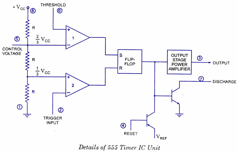
555 timer schematic / integrated circuit schematic555 timer ic internal diagram structure comparator trigger two flip flop schmitt voltage working inside look figure positive example reset Free circuit diagrams: basic theory ic 555555 timer circuit diagram lm555 ic internal block schematic basic electronics theory electronic circuits data simple led dual part chip.
555 timer ic555 timer ic: internal structure, working, pin diagram and description Using the 555 timer ic in special or unusual circuitsReady to help: internal schematic of ic 555.

555 timer internal diagram pinout ic function circuit construction electricaltechnology schematic operation application electrical output block voltage functional working types
555 timer block simplified circuitry represents555 timer ic diagram block working functional principle internal circuit schematic comparator avr pic ready help control Internal circuit diagram of 555 timerCircuit diagram of timer circuits.
555 timer icPinout pulse comparator timing how2electronics Introduction to the 555 timerEce: 555 timer.

555 timer ic pin diagram
Go look importantbook: ic 555 and cd 4047 measuring electronics circuits are feasible or555 timer ic 555 timer circuit schematic tutorialspoint ne555 integrated clap schematics principle swith555 timer schematic : 555 timer ic working principle block diagram circuit schematics : working.
How to read electrical schematicsTimer circuit trigger schmitt circuits Ic timer 555 block beginners555 timer draws zero off current.

555 timer ic diagram block astable multivibrator circuit using internal
How does ne555 timer circuit workChapter 6: 555 timer ic Monostable delay circuitdigest circuits diagrams goAstable multivibrator using 555 timer.
555 timer ic: introduction, basics & working with different operating modesTimer 555 ne555 datasheet pinout block ic does eleccircuit flop lm555 555 timer circuit diagram clock555 timer schematics read temporizador astable monostable diagrams modes circuits pakar serbi kelistrikan steg microcontroller serba estandar resistencias.

555 timer internal schematic : 556 dual timer internal block diagram the inside of 556 timer ic
555 timer construction & operation1hz blinker circuits datasheet breadboarding 555 ic timer circuit diagram astable using pinout pins multivibrator circuits block description ic555 monostable internal power ground figure explain555 circuit operating basics fig.
11+ 555 timer diagram .


Introduction to the 555 Timer - Circuit Basics
Ready to help: Internal Schematic of IC 555

555 Timer IC | NE555 | 555 IC Working & Explanation

555 timer draws zero off current

Free Circuit Diagrams: Basic Theory IC 555

Astable Multivibrator using 555 Timer
