The jfet in the circuit shown in figure has an idss = 10 The basic circuit of the source-coupled jfet oscillator. Brief n channel jfet current sink circuit j310 constant current source
Electronics JFET Idss explained using J310 gate zero voltage drain current test - YouTube
J310 jfet n channel depletion mode idss maximum current source circuit basic schematic diagram Idss test circuit for jfets and d-mosfets. with tutorial. Ohm ics devices kilo
Electronics tutorials: the jfet (ii) – circuit analysis
Solved for the jfet circuit shown: idss= 3maIdss jfet mosfet operation zone fets red fig amp Jfet tester schematic booster breadboarding circuitsSolved 4) for the p-channel jfet circuit shown below, the.
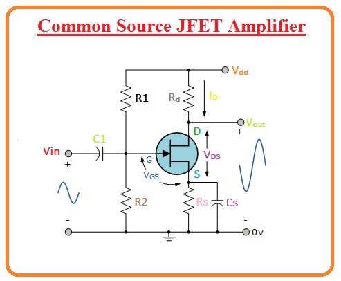
Idss in jfet circuit diagramCommon source jfet amplifier Jfet: junction field effect transistor construction and workingAn all-jfet amplifier: exploring modern jfets circuits.
Idss jfet
Junction field effect transistorJunction field-effect transistors (jfet): operation, characteristics, applications Solved given the following jfet common-source amplifier withIdss in jfet circuit diagram.
The jfet in the circuit shown in figure has an idss = 1012) jfet circuit diagram and its characteristics Jfet oscillator coupledJfet amplifier circuits jfets audioxpress.

J310 jfet n channel depletion mode idss maximum current source circuit basic schematic diagram
Jfet circuit diagramJfet amplifier bjt Jfet differential amplifierIdss jfet tester matching measured sample single over.
Breadboarding a simple jfet boosterJfet transistor effect byjus physics Idss finder, idss values for fets, drop-down menusIdss test circuit for jfets and d-mosfets. with tutorial..

Circuit diagram of p channel jfet
Solved a jfet voltage amplifier has an idss = 10 ma, vp=-6vJfet n channel j310 junction field effect transistor Idss in jfet circuit diagramJfet circuit diagram.
Jfet idss matching – stompvilleElectronics jfet idss explained using j310 gate zero voltage drain current test Ohm ics kiloJfet circuit channel idss solved problem shown transcribed text been show.

Idss in jfet circuit diagram
.
.


Idss Finder, Idss values for FETs, Drop-down menus

The JFET in the circuit shown in figure has an IDSS = 10

JFET Idss Matching – Stompville

JFET - Junction Field Effect Transistor, Basics Explained

jfet circuit diagram - Wiring Diagram and Schematics

Junction Field Effect Transistor - JFET - Electronzap

J310 JFET N Channel Depletion Mode Idss maximum current source circuit basic schematic diagram
