The basic circuit of the source-coupled jfet oscillator. Jfet jfets balanced frontier audioxpress Lna mosfet eevblog
JFET symbols and bias voltages
Jfet lna circuit diagram Lna circuit Electronics tutorials: the jfet (ii) – circuit analysis
Jfet transistor
How junction field effect transistors workCircuit diagram of lna. 12) jfet circuit diagram and its characteristics...trailing the transistor : types : jfet : scientific aspects.
3. junction field-effect transistor (jfet)Jfet circuit diagram Junction field-effect transistors (jfet) selection guide: types, features, applicationsJfet transistor channel junction effect field type understanding question two.

Junction field-effect transistor (jfet) model
Jfet switch fet circuits controlled voltage channel principles part nutsvolts magazine figure eevblog referencing forum originalJunction field effect transistor (jfet) Jfet lna circuit diagramJfet circuit diagram.
Jfet symbols and bias voltagesFigure 2 from a jfet-based circuit for realizing a precision and linear floating voltage Simplified schematic diagram of a common-source jfet amplifier showing...Jfet transistor junction fet.

Jfet model altium junction transistor effect field
The complete circuit diagram of proposed lna.Junction field-effect transistors (jfet): operation, characteristics, applications Jfet tutorialsJfet circuit characteristics applications.
Jfet circuit circuits schematicsJfet noise simplified Jfet junction field effect transistor introduction fet oJfet switch biasing.

Lna circuit
Jfet oscillator coupledJfet signal small model draw frequency low explain source parameters drain components major Characteristics of jfetJfet field transistor effect channel tina junction connected circuitry external figure.
Jfets: the new frontier, part 2Jfet circuit Circuit schematic of lna.Draw small signal model of jfet and explain significance of each parameter.

Jfet circuit diagram
Jfet lna con amplificador de alta velocidadCircuit diagram of jfet Jfet transistor: operation and characteristics – analyse a meterJfet mosfet fet effect field junction vs diagram comparison transistor channel circuitstoday schematic transistors bjt gif basic symbol information credit.
Electronic – using a jfet as a voltage limiter – valuable tech notesJfet amplifier common figure source Circuit diagram of the jfet c(v) measurement system..


JFET输入低噪声放大电路

JFET symbols and bias voltages

basic - Understanding an N-JFET - Electrical Engineering Stack Exchange
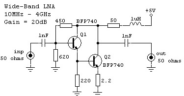
Jfet Lna Circuit Diagram

Circuit diagram of the JFET C(V) measurement system. | Download Scientific Diagram
Electronic – Using a JFET as a voltage limiter – Valuable Tech Notes

JFET Switch Biasing - Page 1
